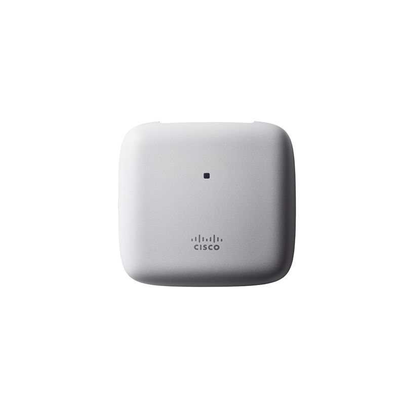
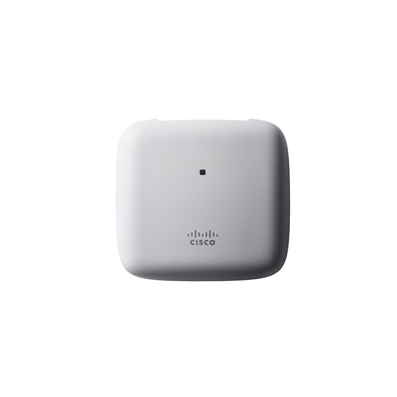
CISCO AIR-AP1815I-Q-K9 Aironet 1815i Access Points

- 763 412 7282
- +86 010 69614620
AIR-AP1815I-Q-K9 Buying Guide
AIR-AP1815I-Q-K9 Cisco Aironet 1815I Dual-band WiFi 5 Access Point is listed by YYST Global for buyers looking for CISCO Aironet 1815i Access Points. AIR-AP1815I-Q-K9 CISCO wireless networking hardware for campus WLAN projects. Contact YYST Global for stock, lead time and quote support. The listed condition is New Factory Sealed. The reference price is US$ 200.00. Contact our sales team to confirm stock, lead time, warranty and configuration before ordering.
- Model: AIR-AP1815I-Q-K9
- Brand: CISCO
- Category: Cisco Aironet 1815i Access Points
- Condition: New Factory Sealed
- Reference price: US$ 200.00
AIR-AP1815I-Q-K9 Overview
AIR-AP1815I-Q-K9 is a CISCO wireless networking hardware listed by YYST Global for campus WLAN expansion, controller replacement, access point rollout and wireless refresh projects. This page is intended for buyers comparing replacement parts, project supply, spare inventory and quote options.
YYST Global helps enterprise customers confirm model information, product category, condition, availability and sourcing route before purchase. For time-sensitive projects, send the model number and required quantity so our sales team can check stock, lead time and compatible alternatives.
Product name: AIR-AP1815I-Q-K9 Cisco Aironet 1815I Dual-band WiFi 5 Access Point. Category: Cisco Aironet 1815i Access Points. Condition: New Factory Sealed.
AIR-AP1815I-Q-K9 Specification
| Datasheet series | Cisco Catalyst 9100 Access Points |
| Exact model | AIR-AP1815I-Q-K9 |
| Wireless role | Enterprise indoor/outdoor access point; confirm antenna, regulatory domain and mounting requirement |
| Wireless generation | Enterprise wireless access point family |
| Power requirement | Confirm PoE standard, injector or power adapter requirement before purchase |
| Deployment check | Confirm controller/cloud management compatibility, country domain, mounting kit and license requirement |
| Procurement validation | Confirm exact part number, condition, licenses, accessories, power/airflow option, warranty, stock and lead time before purchase |
| Official datasheet | Cisco Catalyst wireless access points official product page |
| Product Name | Cisco Aironet 1815i | |||||||
| Part Number | AIR-AP1815i-x-K9: Dual-band, controller-based 802.11a/g/n/ac, Wave 2 | |||||||
| Authentication and security | ● Advanced Encryption Standard (AES) for Wi-Fi Protected Access 3 (WPA3), WPA2, WPA | |||||||
| ● 802.1X, RADIUS Authentication, Authorization, and Accounting (AAA) | ||||||||
| ● 802.11r | ||||||||
| ● 802.11i | ||||||||
| Software | ● Cisco Unified Wireless Network Software with AireOS Wireless Controllers Release 8.3.112.0/83MR1 or later | |||||||
| ● Cisco Mobility Express | ||||||||
| Supported WLAN controllers | ● Cisco 2500 Series Wireless Controllers, Cisco 3500 Series Wireless Controllers, Cisco Wireless Controller Module for ISR G2, Cisco Wireless Services Module 2 (WiSM2) for Catalyst ® 6500 Series Switches, Cisco 5500 Series Wireless Controllers, Cisco Flex ® 7500 Series Wireless Controllers, Cisco 8500 Series Wireless Controllers, Cisco 9800 series Wireless Controllers. | |||||||
| ● Cisco Mobility Express | ||||||||
| Maximum clients | ● Maximum number of associated wireless clients: 200 per Wi-Fi radio, in total 400 clients per access point | |||||||
| 802.11ac | ● 2x2 single-user/multiuser MIMO with two spatial streams | |||||||
| ● Maximal Ratio Combining (MRC) | ||||||||
| ● 20-, 40- and 80-MHz channels | ||||||||
| ● PHY data rates up to 866.7 Mbps (80 MHz on 5 GHz) | ||||||||
| ● Packet aggregation: A-MPDU (Tx/Rx), A-MSDU (Rx) | ||||||||
| ● 802.11 Dynamic Frequency Selection (DFS) | ||||||||
| ● Cyclic Shift Diversity (CSD) support | ||||||||
| Ethernet ports | ● Authentication with 802.1X or MAC filtered | |||||||
| ● Dynamic VLAN or per port | ||||||||
| ● Traffic locally switched or tunneled back to wireless LAN controller | ||||||||
| Bluetooth (future availability) | ● Integrated Bluetooth 4.1 (including BLE) radio | |||||||
| ● Maximum transmit power: 4 dBm | ||||||||
| ● Antenna gain: 2 dBi | ||||||||
| Data rates supported | 802.11a: 6, 9, 12, 18, 24, 36, 48, 54 Mbps | |||||||
| 802.11b/g: 1, 2, 5.5, 6, 9, 11, 12, 18, 24, 36, 48, 54 Mbps | ||||||||
| 802.11n data rates on 2.4 GHz: | ||||||||
| MCS Index1 | GI2 = 800 ns | GI = 400 ns | ||||||
| 20-MHz Rate (Mbps) | 20-MHz Rate (Mbps) | |||||||
| 0 | 6.5 | 7.2 | ||||||
| 1 | 13 | 14.4 | ||||||
| 2 | 19.5 | 21.7 | ||||||
| 3 | 26 | 28.9 | ||||||
| 4 | 39 | 43.3 | ||||||
| 5 | 52 | 57.8 | ||||||
| 6 | 58.5 | 65 | ||||||
| 7 | 65 | 72.2 | ||||||
| 8 | 13 | 14.4 | ||||||
| 9 | 26 | 28.9 | ||||||
| 10 | 39 | 43.3 | ||||||
| 11 | 52 | 57.8 | ||||||
| 12 | 78 | 86.7 | ||||||
| 13 | 104 | 115.6 | ||||||
| 14 | 117 | 130 | ||||||
| 15 | 130 | 144.4 | ||||||
| 802.11ac data rates on 5 GHz: | ||||||||
| MCS Index | Spatial Streams | GI = 800 ns | GI = 400 ns | |||||
| 20-MHz | 40-MHz | 80-MHz | 20-MHz | 40-MHz | 80-MHz | |||
| Rate | Rate | Rate | Rate | Rate (Mbps) | Rate | |||
| (Mbps) | (Mbps) | (Mbps) | (Mbps) | (Mbps) | ||||
| 1 | 6.5 | 13.5 | 29.3 | 7.2 | 15 | 32.5 | ||
| 1 | 13 | 27 | 58.5 | 14.4 | 30 | 65 | ||
| 1 | 19.5 | 40.5 | 87.8 | 21.7 | 45 | 97.5 | ||
| 1 | 26 | 54 | 117 | 28.9 | 60 | 130 | ||
| 1 | 39 | 81 | 175.5 | 43.3 | 90 | 195 | ||
| 1 | 52 | 108 | 234 | 57.8 | 120 | 260 | ||
| 1 | 58.5 | 121.5 | 263.3 | 65 | 135 | 292.5 | ||
| 1 | 65 | 135 | 292.5 | 72.2 | 150 | 325 | ||
| 1 | 78 | 162 | 351 | 86.7 | 180 | 390 | ||
| 1 | – | 180 | 390 | – | 200 | 433.3 | ||
| 2 | 13 | 27 | 58.5 | 14.4 | 30 | 65 | ||
| 2 | 26 | 54 | 117 | 28.9 | 60 | 130 | ||
| 2 | 39 | 81 | 175.5 | 43.3 | 90 | 195 | ||
| 2 | 52 | 108 | 234 | 57.8 | 120 | 260 | ||
| 2 | 78 | 162 | 351 | 86.7 | 180 | 390 | ||
| 2 | 104 | 216 | 468 | 115.6 | 240 | 520 | ||
| 2 | 117 | 243 | 526.5 | 130 | 270 | 585 | ||
| 2 | 130 | 270 | 585 | 144.4 | 300 | 650 | ||
| 2 | 156 | 324 | 702 | 173.3 | 360 | 780 | ||
| 2 | – | 360 | 780 | – | 400 | 866.7 | ||
| Maximum number of non-overlapping channels | A (A regulatory domain): | K (K regulatory domain): | ||||||
| ● 2.412 to 2.462 GHz; 11 channels | ● 2.412 to 2.472 GHz; 13 channels | |||||||
| ● 5.180 to 5.320 GHz; 8 channels | ● 5.180 to 5.320 GHz; 8 channels | |||||||
| ● 5.500 to 5.700 GHz; 8 channels (excludes 5.600 to 5.640 GHz) | ● 5.500 to 5.620 GHz; 7 channels | |||||||
| ● 5.745 to 5.825 GHz; 5 channels | ● 5.745 to 5.805 GHz; 4 channels | |||||||
| B (B regulatory domain): | N (N regulatory domain): | |||||||
| ● 2.412 to 2.462 GHz; 11 channels | ● 2.412 to 2.462 GHz; 11 channels | |||||||
| ● 5.180 to 5.320 GHz; 8 channels | ● 5.180 to 5.320 GHz; 8 channels | |||||||
| ● 5.500 to 5.720 GHz; 12 channels | ● 5.745 to 5.825 GHz; 5 channels | |||||||
| ● 5.745 to 5.825 GHz; 5 channels | Q (Q regulatory domain): | |||||||
| C (C regulatory domain): | ● 2.412 to 2.472 GHz; 13 channels | |||||||
| ● 2.412 to 2.472 GHz; 13 channels | ● 5.180 to 5.320 GHz; 8 channels | |||||||
| ● 5.745 to 5.825 GHz; 5 channels | ● 5.500 to 5.700 GHz; 11 channels | |||||||
| D (D regulatory domain): | R (R regulatory domain): | |||||||
| ● 2.412 to 2.462 GHz; 11 channels | ● 2.412 to 2.472 GHz; 13 channels | |||||||
| ● 5.180 to 5.320 GHz; 8 channels | ● 5.180 to 5.320 GHz; 8 channels | |||||||
| ● 5.745 to 5.825 GHz; 5 channels | ● 5.660 to 5.700 GHz; 3 channels | |||||||
| E (E regulatory domain): | ● 5.745 to 5.805 GHz; 4 channels | |||||||
| ● 2.412 to 2.472 GHz; 13 channels | S (S regulatory domain): | |||||||
| ● 5.180 to 5.320 GHz; 8 channels | ● 2.412 to 2.472 GHz; 13 channels | |||||||
| ● 5.500 to 5.700 GHz; 8 channels | ● 5.180 to 5.320 GHz; 8 channels | |||||||
| (excludes 5.600 to 5.640 GHz) | ● 5.500 to 5.700 GHz; 11 channels | |||||||
| F (F regulatory domain): | ● 5.745 to 5.825 GHz; 5 channels | |||||||
| ● 2.412 to 2.472 GHz; 13 channels | T (T regulatory domain): | |||||||
| ● 5.250 to 5.350 GHz; 4 channels | ● 2.412 to 2.462 GHz; 11 channels | |||||||
| ● 5.725 to 5.825 GHz; 4 channels | ● 5.280 to 5.320 GHz; 3 channels | |||||||
| G (G regulatory domain): | ● 5.500 to 5.700 GHz; 8 channels | |||||||
| ● 2.412 to 2.472 GHz; 13 channels | (excludes 5.600 to 5.640 GHz) | |||||||
| ● 5.745 to 5.865 GHz; 7 channels | ● 5.745 to 5.825 GHz; 5 channels | |||||||
| H (H regulatory domain): | Z (Z regulatory domain): | |||||||
| ● 2.412 to 2.472 GHz; 13 channels | ● 2.412 to 2.462 GHz; 11 channels | |||||||
| ● 5.180 to 5.320 GHz; 8 channels | ● 5.180 to 5.320 GHz; 8 channels | |||||||
| ● 5.745 to 5.825 GHz; 5 channels | ● 5.500 to 5.700 GHz; 8 channels | |||||||
| I (I regulatory domain): | (excludes 5.600 to 5.640 GHz) | |||||||
| ● 2.412 to 2.472 GHz; 13 channels | ● 5.745 to 5.825 GHz; 5 channels | |||||||
| ● 5.180 to 5.320 GHz; 8 channels | ||||||||
| Note: This varies by regulatory domain. Refer to the product documentation for specific details for each regulatory domain. | ||||||||
| Available transmit power settings | 2.4 GHz | 5 GHz | ||||||
| 20 dBm (100 mW) | 20 dBm (100 mW) | |||||||
| 17 dBm (50 mW) | 17 dBm (50 mW) | |||||||
| 14 dBm (25 mW) | 14 dBm (25 mW) | |||||||
| 11 dBm (12.5 mW) | 11 dBm (12.5 mW) | |||||||
| 8 dBm (6.25 mW) | 8 dBm (6.25 mW) | |||||||
| 5 dBm (3.13 mW) | 5 dBm (3.13 mW) | |||||||
| 2 dBm (1.56 mW) | 2 dBm (1.56 mW) | |||||||
| -1 dBm (0.78 mW) | -1 dBm (0.78mW) | |||||||
| Note: The maximum power setting will vary by channel and according to individual country regulations. Refer to the product documentation for specific details. | ||||||||
| Integrated antennas | ● 2.4 GHz, gain 2 dBi | |||||||
| ● 5 GHz, gain 4 dBi | ||||||||
| Interfaces | ● 1 x 10/100/1000BASE-T autosensing (RJ-45), Power over Ethernet (PoE) | |||||||
| ● Management console port (RJ-45) | ||||||||
| Indicators | ● Status LED indicates boot loader status, association status, operating status, boot loader warnings, boot loader errors | |||||||
| Dimensions (W x L x H) | ● Access point (without mounting bracket): 6 x 6 x 1.3 in (150.8 x 150.8 x 33 mm) | |||||||
| Weight | ● Access point without mounting bracket or any other accessories: 14 oz (400 g) | |||||||
| Environmental | ● Operating | |||||||
| ◦ Temperature: 32° to 104°F (0° to 40°C) | ||||||||
| ◦ Humidity: 10% to 90% (noncondensing) | ||||||||
| ◦ Max. altitude: 9843 ft (3000 m) @ 40°C | ||||||||
| ● Nonoperating (storage and transportation) | ||||||||
| ◦ Temperature: -22° to 158°F (-30° to 70°C) | ||||||||
| ◦ Humidity: 10% to 90% (noncondensing) | ||||||||
| ◦ Max. altitude: 15,000 ft (4500 m) @ 25°C | ||||||||
| System | ● 1 GB DRAM | |||||||
| ● 256 MB flash | ||||||||
| ● 710 MHz quad core | ||||||||
| Input power requirements | ● Power injector: AIR-PWRINJ5= or AIR-PWRINJ6= | |||||||
| Powering options | ● 802.3af/at Ethernet switch | |||||||
| ● Optional Cisco power injectors (AIR-PWRINJ5=, AIR-PWRINJ6=) | ||||||||
| Power draw | ● 8.3W (maximum, on PoE) | |||||||
| Physical security | ● Torx security screw, included with the access point | |||||||
| Mounting | ● Included with the access point: mounting bracket AIR-AP-BRACKET8 | |||||||
| Accessories | ● Mounting bracket: AIR-AP-BRACKET8= (available as spare) | |||||||
| ● Physical security kit: AIR-SEC-50= (sold separately), with 50 pcs. Security screws used to secure access point onto wall-mounting bracket, 50 pcs. RJ-45 caps and 2 pcs. unlock keys used to block physical access to Ethernet ports | ||||||||
| Warranty | Limited Lifetime Hardware Warranty | |||||||
| Compliance | ● Safety: | |||||||
| ◦ UL 60950-1 | ||||||||
| ◦ CAN/CSA-C22.2 No. 60950-1 | ||||||||
| ◦ UL 2043 | ||||||||
| ◦ IEC 60950-1 | ||||||||
| ◦ EN 60950-1 | ||||||||
| ◦ EN 60601-1-2 | ||||||||
| ● Radio approvals: | ||||||||
| ◦ FCC Part 15.247, 15.407 | ||||||||
| ◦ RSS-247 (Canada) | ||||||||
| ◦ EN 300.328, EN 301.893 (Europe) | ||||||||
| ◦ ARIB-STD 66 (Japan) | ||||||||
| ◦ ARIB-STD T71 (Japan) | ||||||||
| ◦ EMI and susceptibility (Class B) | ||||||||
| ◦ FCC Part 15.107 and 15.109 | ||||||||
| ◦ ICES-003 (Canada) | ||||||||
| ◦ VCCI (Japan) | ||||||||
| ◦ EN 301.489-1 and -17 (Europe) | ||||||||
| ◦ EN 50385 | ||||||||
| ● IEEE standards: | ||||||||
| ◦ IEEE 802.11a/b/g, 802.11n, 802.11h, 802.11d | ||||||||
| ◦ IEEE 802.11ac | ||||||||
| ● Security: | ||||||||
| ◦ 802.11i, WPA3, WPA2, WPA | ||||||||
| ◦ 802.1X | ||||||||
| ◦ AES | ||||||||
| ● Extensible Authentication Protocol (EAP) types: | ||||||||
| ◦ EAP-Transport Layer Security (TLS) | ||||||||
| ◦ EAP-Tunneled TLS (TTLS) or Microsoft Challenge Handshake Authentication Protocol Version 2 (MSCHAPv2) | ||||||||
| ◦ Protected EAP (PEAP) v0 or EAP-MSCHAPv2 | ||||||||
| ◦ EAP-Flexible Authentication via Secure Tunneling (FAST) | ||||||||
| ◦ PEAP v1 or EAP-Generic Token Card (GTC) | ||||||||
| ◦ EAP-Subscriber Identity Module (SIM) | ||||||||
| ● Multimedia: | ||||||||
| ◦ Wi-Fi Multimedia (WMM) | ||||||||
| ● Other: | ||||||||
| ◦ FCC Bulletin OET-65C | ||||||||
| ◦ RSS-102 | ||||||||
| 1 MCS Index: The Modulation and Coding Scheme (MCS) index determines the number of spatial streams, the modulation, the coding rate, and data rate values. | ||||||||
| 2 A Guard Interval (GI) between symbols helps receivers overcome the effects of multipath delay spreads. | ||||||||
| Transmit power and receive sensitivity (1815i) | |||||
| 2.4-GHz Radio | 5-GHz Radio | ||||
| Spatial Streams | Total TX Power (dBm) | RX Sensitivity (dBm) | Total TX Power (dBm) | RX Sensitivity (dBm) | |
| 802.11/11b | |||||
| 1 Mbps | 1 | 17 | -98 | NA | NA |
| 11 Mbps | 1 | 17 | -89 | NA | NA |
| 802.11a/g | |||||
| 6 Mbps | 1 | 20 | -94 | 17 | -94 |
| 24 Mbps | 1 | 20 | -87 | 20 | -87 |
| 54 Mbps | 1 | 20 | -78 | 18 | -78 |
| 802.11n HT20 | |||||
| MSC0 | 1 | 20 | -93 | 20 | -93 |
| MSC4 | 1 | 20 | -83 | 18 | -82 |
| MSC7 | 1 | 20 | -75 | 16 | -75 |
| MSC8 | 2 | 20 | -90 | 20 | -90 |
| MSC12 | 2 | 20 | -80 | 18 | -79 |
| MSC15 | 2 | 20 | -72 | 16 | -72 |
| 802.11n HT40 | |||||
| MSC0 | 1 | 20 | -90 | ||
| MSC4 | 1 | 18 | -79 | ||
| MSC7 | 1 | 16 | -72 | ||
| MSC8 | 2 | 20 | -87 | ||
| MSC12 | 2 | 18 | -76 | ||
| MSC15 | 2 | 16 | -69 | ||
| 802.11ac VHT20 | |||||
| MSC0 | 1 | 20 | -93 | ||
| MSC4 | 1 | 18 | -82 | ||
| MSC7 | 1 | 16 | -75 | ||
| MSC8 | 1 | 15 | -71 | ||
| MSC0 | 2 | 20 | -90 | ||
| MSC4 | 2 | 18 | -79 | ||
| MSC7 | 2 | 16 | -72 | ||
| MSC8 | 2 | 15 | -68 | ||
| 802.11ac VHT40 | |||||
| MSC0 | 1 | 20 | -90 | ||
| MSC4 | 1 | 18 | -79 | ||
| MSC7 | 1 | 16 | -72 | ||
| MSC8 | 1 | 15 | -68 | ||
| MSC9 | 1 | 15 | -66 | ||
| MSC0 | 2 | 20 | -87 | ||
| MSC4 | 2 | 18 | -76 | ||
| MSC7 | 2 | 16 | -69 | ||
| MSC8 | 2 | 15 | -65 | ||
| MSC9 | 2 | 15 | -63 | ||
| 802.11ac VHT80 | |||||
| MSC0 | 1 | 20 | -87 | ||
| MSC4 | 1 | 18 | -77 | ||
| MSC7 | 1 | 16 | -69 | ||
| MSC8 | 1 | 15 | -65 | ||
| MSC9 | 1 | 15 | -63 | ||
| MSC0 | 2 | 20 | -84 | ||
| MSC4 | 2 | 18 | -74 | ||
| MSC7 | 2 | 16 | -66 | ||
| MSC8 | 2 | 15 | -62 | ||
| MSC9 | 2 | 15 | -60 | ||
| Note: The maximum power setting will vary by channel and according to individual country regulations. Refer to the product documentation for specific details. | |||||
AIR-AP1815I-Q-K9 Warranty
 | Low Price Guarantee |  | Quality Assurance |
 | Free CCIE Expert Technical Support |  | Commodity Refund Guarantee |
 | Diversified and Flexible Transportation Services |  | Standard Policy |
AIR-AP1815I-Q-K9 FAQ
What is AIR-AP1815I-Q-K9?
AIR-AP1815I-Q-K9 Cisco Aironet 1815I Dual-band WiFi 5 Access Point is a CISCO Aironet 1815i Access Points product supplied by YYST Global for enterprise IT procurement and infrastructure projects.
What wireless or client capacity is listed for AIR-AP1815I-Q-K9?
For AIR-AP1815I-Q-K9, the official specification lists wireless role as Enterprise indoor/outdoor access point; confirm antenna, regulatory domain and mounting requirement. Confirm the exact SKU, suffix and hardware revision against the official manufacturer reference before ordering.
What interfaces and ports does AIR-AP1815I-Q-K9 provide?
For AIR-AP1815I-Q-K9, the official specification lists ethernet ports as ● Authentication with 802.1X or MAC filtered. Confirm the exact SKU, suffix and hardware revision against the official manufacturer reference before ordering.
Is AIR-AP1815I-Q-K9 available from YYST Global?
AIR-AP1815I-Q-K9 is listed as in stock at YYST Global. Contact the sales team to confirm the required quantity, exact configuration, delivery destination and current lead time before ordering.
What is the price of AIR-AP1815I-Q-K9?
The current reference price for AIR-AP1815I-Q-K9 is US$ 200.00. Final pricing can change based on stock, quantity, configuration and delivery destination.
Related products
Related AIR-AP1815I-Q-K9
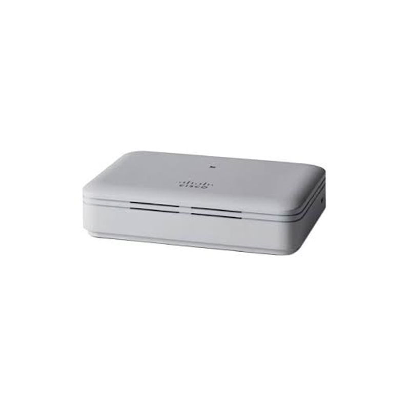
AIR-AP1815T-H-K9 Cisco Aironet 1815T Dual-radio OfficeExtend AP
AIR-AP1815T-H-K9 Cisco Cisco Aironet 1815i Access Points supplied by YYST Global. Contact us to confirm stock, lead time, warranty, condition and global shipping options.
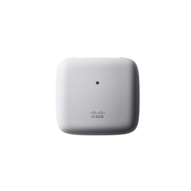
AIR-AP1815I-I-K9 Cisco Aironet 1815I 802.11ac Bluetooth 4.1 AP
AIR-AP1815I-I-K9 CISCO wireless networking hardware for campus WLAN projects. Contact YYST Global for stock, lead time and quote support.
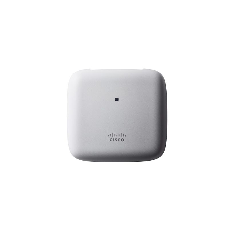
AIR-AP1815I-A-K9C Cisco Aironet 1815I WiFi 5 AP with Mobility Express
AIR-AP1815I-A-K9C CISCO wireless networking hardware for campus WLAN projects. Contact YYST Global for stock, lead time and quote support.
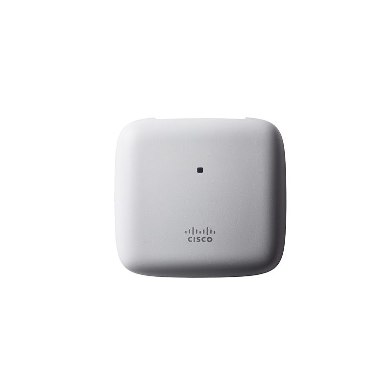
AIR-AP1815I-A-K9 Cisco Aironet 1815I 802.11ac Wave 2 Access Point
AIR-AP1815I-A-K9 CISCO wireless networking hardware for campus WLAN projects. Contact YYST Global for stock, lead time and quote support.
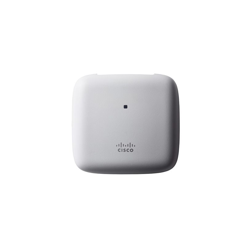
AIR-AP1815I-N-K9 Cisco Aironet 1815I WiFi 5 Wave 2 Access Point
AIR-AP1815I-N-K9 CISCO wireless networking hardware for campus WLAN projects. Contact YYST Global for stock, lead time and quote support.
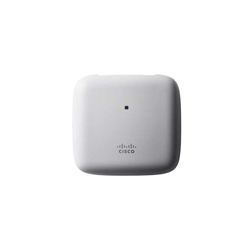
AIR-AP1815I-I-K9C Cisco Aironet 1815I 802.11ac Wave 2 Access Point
AIR-AP1815I-I-K9C CISCO wireless networking hardware for campus WLAN projects. Contact YYST Global for stock, lead time and quote support.
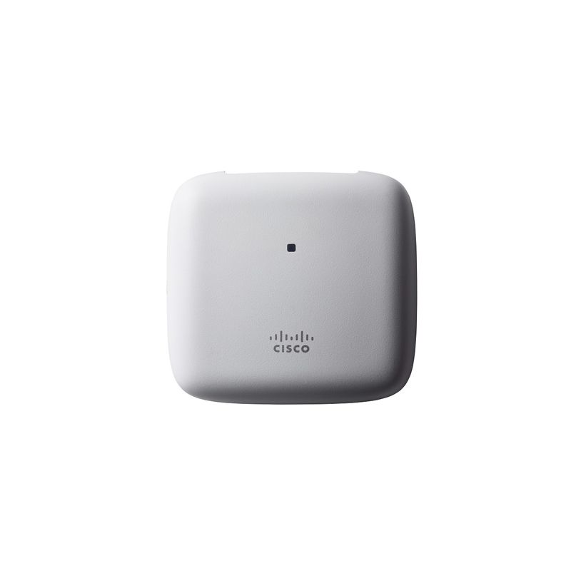
AIR-AP1815I-B-K9 Cisco Aironet 1815I 2x2:2 MU-MIMO WiFi 5 AP
AIR-AP1815I-B-K9 CISCO wireless networking hardware for campus WLAN projects. Contact YYST Global for stock, lead time and quote support.
AIR-AP1815I-Z-K9C Cisco 1815I SS MU-MIMO AP with Mobility Express
AIR-AP1815I-Z-K9C CISCO wireless networking hardware for campus WLAN projects. Contact YYST Global for stock, lead time and quote support.
