
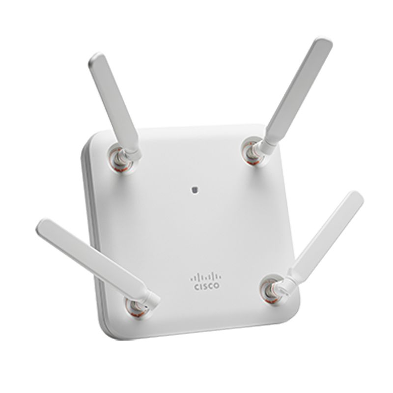
AIR-AP1852E-B-K9C Cisco Aironet 1852e Enterprise-class 4x4 MIMO AP

- 763 412 7282
- +86 010 69614620
AIR-AP1852E-B-K9C Overview
AIR-AP1852E-B-K9C exact order identity
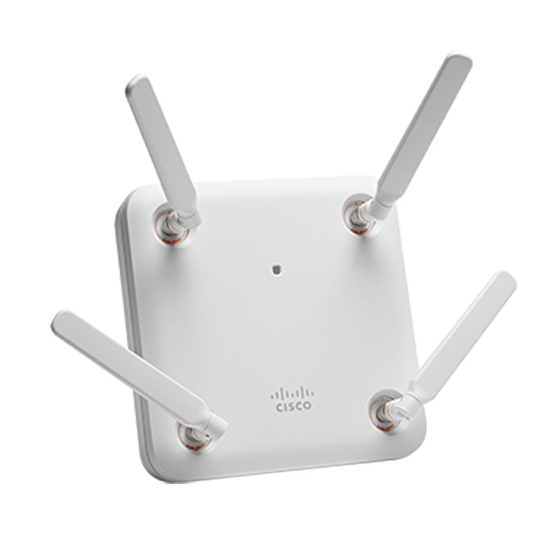
AIR-AP1852E-B-K9C is a 1852e indoor access point for separately purchased external antennas in the Cisco Aironet 1850 Series. This exact SKU combines regulatory-domain token B with a single-unit configurable K9C order. The platform is a dual-band 802.11ac Wave 2 access point with four 5 GHz spatial streams in single-user operation and three in multiuser operation.
Antenna and environmental boundary
Cisco states that external antennas are sold separately and certifies the platform for antenna gains up to 6 dBi at both 2.4 and 5 GHz. Record the approved Cisco antenna part numbers, four radio paths, gain, pattern, cable loss, connectors and mounting orientation. A compatible connector alone is not regulatory or RF-design evidence.
Order and controller boundary
Cisco lists K9C as a configurable controller-based order, and its lifecycle table describes affected K9C lines as Mobility Express products. Retain the final domain and software role on the quotation and received unit. Prove the intended controller or Mobility Express state instead of inferring it from the suffix alone.
B regulatory-domain evidence
Cisco lists this profile as 2.4 GHz channels 1-11; 5 GHz blocks at 5.180-5.320, 5.500-5.720, and 5.745-5.825 GHz. The B plan contains a broad middle 5 GHz range followed by a separate upper block. Capacity planning should identify which radios use each block and should not copy a narrower domain's channel template. Retain a controller export showing the enabled lower, middle and upper channel sets. Compare the installed country setting, dynamic channel assignment and survey plan before accepting the site.
Procurement inference: the comparatively broad middle range and separate upper range can influence how capacity is distributed across radios. Preserve the survey's planned channel groups and compare them with the controller's dynamic assignment after a representative operating period. If the destination authorization narrows the available set, update the capacity calculation and acceptance record rather than leaving a B-profile assumption in the design.
Power and interface boundary
The 1852 provides a PoE Gigabit uplink and a Gigabit AUX port for link aggregation. Cisco states that 802.3af disables AUX and USB on both antenna forms and reduces the 1852e 2.4 GHz radio from 3x4 to 2x3. Record negotiated power before promising the complete interface and radio state.
Deployment evidence worksheet
Power-state acceptance
Measure power after the access point has joined its controller and the planned radios and services are active. Record switch model, port, negotiated power level, LLDP result and any reduced-capability warning. An idle boot result is not sufficient evidence for the deployed power budget. If an injector is proposed, verify its supported use and include its exact identity in the maintained bill of materials rather than treating it as an unspecified accessory. The 1852 draws up to 20.9 W; 802.3af also disables AUX Ethernet and USB, while the external-antenna 1852e reduces its 2.4 GHz radio from 3x4 to 2x3.
Ethernet and cabling proof
Preserve the permanent-link test, patch-lead identities, switch port, negotiated Ethernet rate and error counters. Investigate pair faults, excessive length or rate fallback before wireless acceptance begins. A link light only proves connectivity at some rate; it does not demonstrate the intended uplink performance. Tie the cable result to the AP serial so a later throughput problem can be separated from radio, controller and wired-path causes. The platform has one PoE Gigabit interface and one Gigabit AUX interface used for link aggregation, so preserve both link states and the power condition under which AUX is available.
Survey-to-install reconciliation
Attach the approved RF survey location, mounting height, orientation, expected client density, channel width and neighboring-radio assumptions to the order. After installation, compare measured coverage and interference with that design. If ceiling construction, antenna placement or obstructions changed, document the deviation and repeat the affected measurements. This provides a site-specific acceptance reason for the exact unit instead of relying on a family data sheet alone. Relate the survey result to the 1852's 4x4:4 single-user and 4x4:3 multiuser 5 GHz design rather than treating the published 1.7 Gbps PHY rate as measured site throughput.
Mechanical installation record
List the bracket, ceiling or wall interface, enclosure requirement, safety restraint, service clearance and cable-entry plan before scheduling installation. Receiving should identify missing mechanical items before the access point reaches site. Photograph the mounted label and final cable entry, then record how the unit can be reached for replacement. A complete electronic order can still be an unusable deployment kit when mechanical dependencies are omitted. The 1852i and 1852e have different operating-temperature ranges, and an external-antenna deployment also requires a complete cable and mounting bill of materials.
Roaming acceptance
Define the neighboring access points and client types used for roaming validation. Record handoff behavior, interruption observed, authentication result and controller events along the intended movement path. Compare the outcome with the site's design target rather than declaring success from static association. Where this unit replaces an older AP, test both entry and exit from its cell so a local improvement does not hide a boundary problem. When replacing a neighboring legacy AP, preserve roaming evidence in both directions and compare it with the 1852's installed radio and channel state.
Capacity observation
Define the expected concurrent clients, application mix, airtime utilization and channel-width assumptions for this location. After commissioning, capture radio utilization, retry behavior and representative throughput during a meaningful load period. Compare the observation with the survey design and state any shortfall. A peak link rate from a data sheet is not a site capacity result and should not replace measured operating evidence. Capacity acceptance should show actual client mix, airtime and retries under the available regulatory-domain channels, not only a maximum PHY figure.
Replacement dependency map
Map this unit to controller, licenses, authentication services, switch power, cable, bracket, antenna design and monitoring objects. For an end-of-sale platform, state which dependencies can be reused by the planned Catalyst migration and which require change. A nominal access-point replacement can fail when the surrounding platform was never inventoried. Keep the map with the asset rather than only in a one-time project file. Cisco names the Catalyst 9115AX family as the migration option in the lifecycle bulletin; map controller, power, cabling, mount and antenna changes before replacement.
Operational log retention
Store the initial controller events, switch-port state, radio assignment, channel list and client test results with a consistent asset identifier. Define how long commissioning evidence is retained and who can retrieve it. A later firmware, controller or RF change should add a new dated observation rather than overwrite the original. The resulting history supports lifecycle decisions and distinguishes a new regression from the accepted baseline. Preserve the original 1852 controller join, power mode, AUX state, channel list and client tests so later changes can be compared with an accepted baseline.
Lifecycle decision
Cisco ended sale of the Aironet 1850 Series on 1 May 2022, ended software maintenance on 1 May 2023 and lists 30 April 2027 as the last support date. Cisco identifies Catalyst 9115AX as the migration family. Available inventory does not extend those milestones.
Related Aironet 1852 order records
- AIR-AP1852I-BK910 - compare antenna form and domain evidence.
- AIR-AP1852I-B-K9C - compare antenna form and domain evidence.
- AIR-AP1852E-BK910C - compare order form and domain evidence.
Official evidence: Cisco Aironet 1850 Series data sheet; Cisco Aironet 1850 hardware guide; Cisco Aironet 1850 lifecycle bulletin; and Cisco wireless compliance tool.
AIR-AP1852E-B-K9C Specification
| Exact model / SKU | AIR-AP1852E-B-K9C |
| Exact Cisco PID | AIR-AP1852E-B-K9C |
| Product family | Cisco Aironet 1850 Series |
| Wireless design | 802.11ac Wave 2; 4x4:4 single-user and 4x4:3 multiuser at 5 GHz |
| Antenna form | External antennas, sold separately |
| Published antenna limit | Certified for antenna gains up to 6 dBi at 2.4 and 5 GHz |
| Order form | single-unit configurable K9C order |
| Physical quantity | 1 |
| Regulatory-domain token | B |
| Cisco-listed channel profile | 2.4 GHz channels 1-11; 5 GHz blocks at 5.180-5.320, 5.500-5.720, and 5.745-5.825 GHz |
| Interfaces | PoE Gigabit uplink; Gigabit AUX for link aggregation |
| 802.3af effect | AUX and USB disabled; 1852e 2.4 GHz radio reduces from 3x4 to 2x3 |
| Lifecycle | End of sale 2022-05-01; software maintenance ended 2023-05-01; last support 2027-04-30 |
| Migration family | Cisco Catalyst 9115AX |
| Source match | AIR-AP1852E-B-K9C: 1852E, domain B, single-unit configurable K9C order, quantity 1 |
| Official manufacturer reference | Cisco Aironet 1850 exact lifecycle bulletin |
AIR-AP1852E-B-K9C Warranty
 | Product Quotation |  | Condition and Packaging |
 | Technical Support Enquiry |  | Returns and Replacement |
 | Shipping Arrangements |  | Warranty Terms |
AIR-AP1852E-B-K9C FAQ
What is AIR-AP1852E-B-K9C?
AIR-AP1852E-B-K9C Cisco Aironet 1852e Enterprise-class 4x4 MIMO AP is a CISCO Aironet 1850 Series Access Points product supplied by YYST Global for enterprise IT procurement and infrastructure projects.
What wireless design is listed for AIR-AP1852E-B-K9C?
For AIR-AP1852E-B-K9C, the manufacturer specification lists wireless design as 802.11ac Wave 2; 4x4:4 single-user and 4x4:3 multiuser at 5 GHz.
What antenna form is listed for AIR-AP1852E-B-K9C?
For AIR-AP1852E-B-K9C, the manufacturer specification lists antenna form as External antennas, sold separately.
What published antenna limit is listed for AIR-AP1852E-B-K9C?
For AIR-AP1852E-B-K9C, the manufacturer specification lists published antenna limit as Certified for antenna gains up to 6 dBi at 2.4 and 5 GHz.
Is AIR-AP1852E-B-K9C available from YYST Global?
Contact YYST Global to confirm availability for AIR-AP1852E-B-K9C, the required quantity, exact configuration, delivery destination and current lead time before ordering. A product listing does not confirm current inventory.
Related products
Related AIR-AP1852E-B-K9C
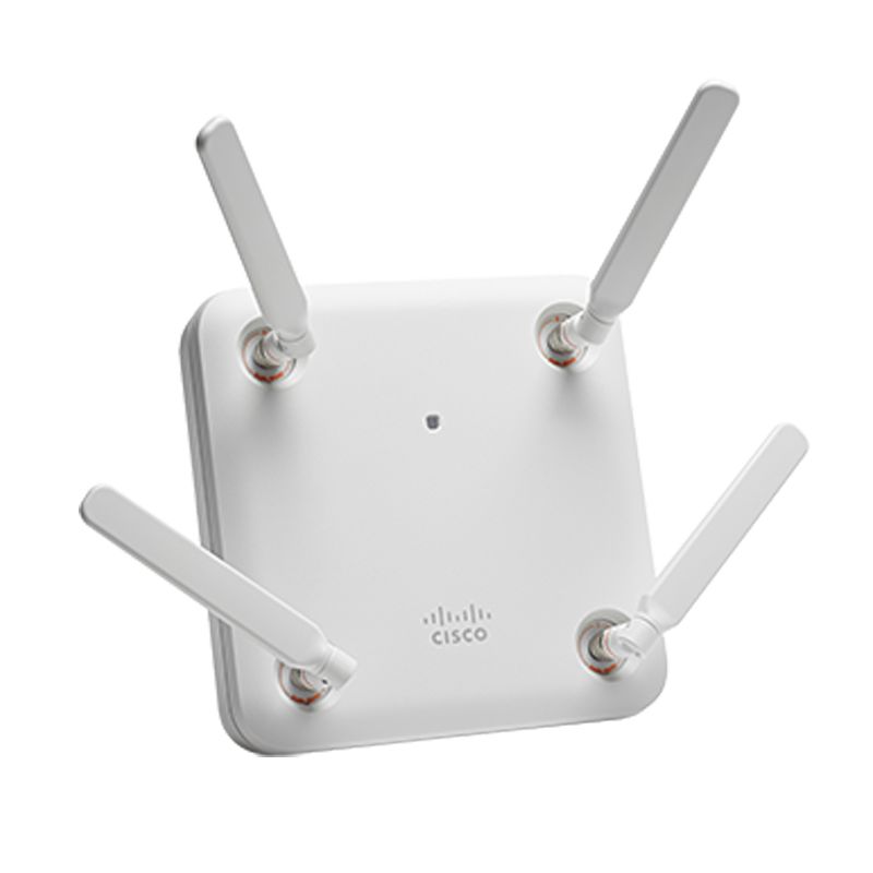
AIR-AP1852E-T-K9 Cisco Aironet 1852e Dual-band 4x4 MIMO Access Point
AIR-AP1852E-T-K9 is a 1852e indoor access point for separately purchased external antennas, supplied as a single-unit fixed-domain K9 order for regulatory-domain token T. Verify destination approval, controller software, PoE mode, exact quantity, antenna or mounting bill of materials and the 30 April 2027 support cutoff before purchase.
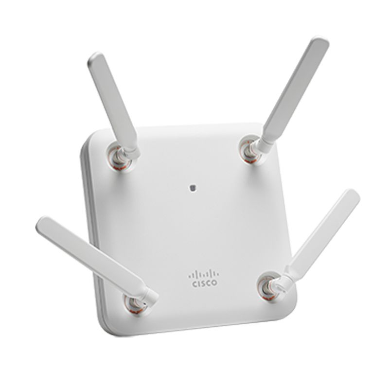
AIR-AP1852E-Q-K9 Cisco Aironet 1852e 4x4 MIMO Access Point
AIR-AP1852E-Q-K9 is a 1852e indoor access point for separately purchased external antennas, supplied as a single-unit fixed-domain K9 order for regulatory-domain token Q. Verify destination approval, controller software, PoE mode, exact quantity, antenna or mounting bill of materials and the 30 April 2027 support cutoff before purchase.
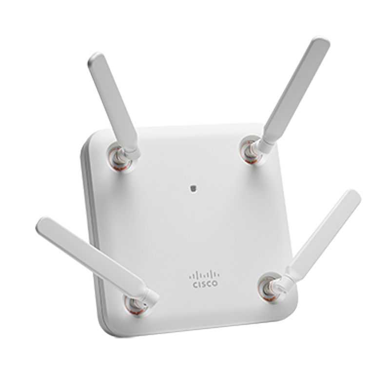
AIR-AP1852E-N-K9 Cisco Aironet 1852e Enterprise-class 4x4 MIMO AP
AIR-AP1852E-N-K9 is a 1852e indoor access point for separately purchased external antennas, supplied as a single-unit fixed-domain K9 order for regulatory-domain token N. Verify destination approval, controller software, PoE mode, exact quantity, antenna or mounting bill of materials and the 30 April 2027 support cutoff before purchase.
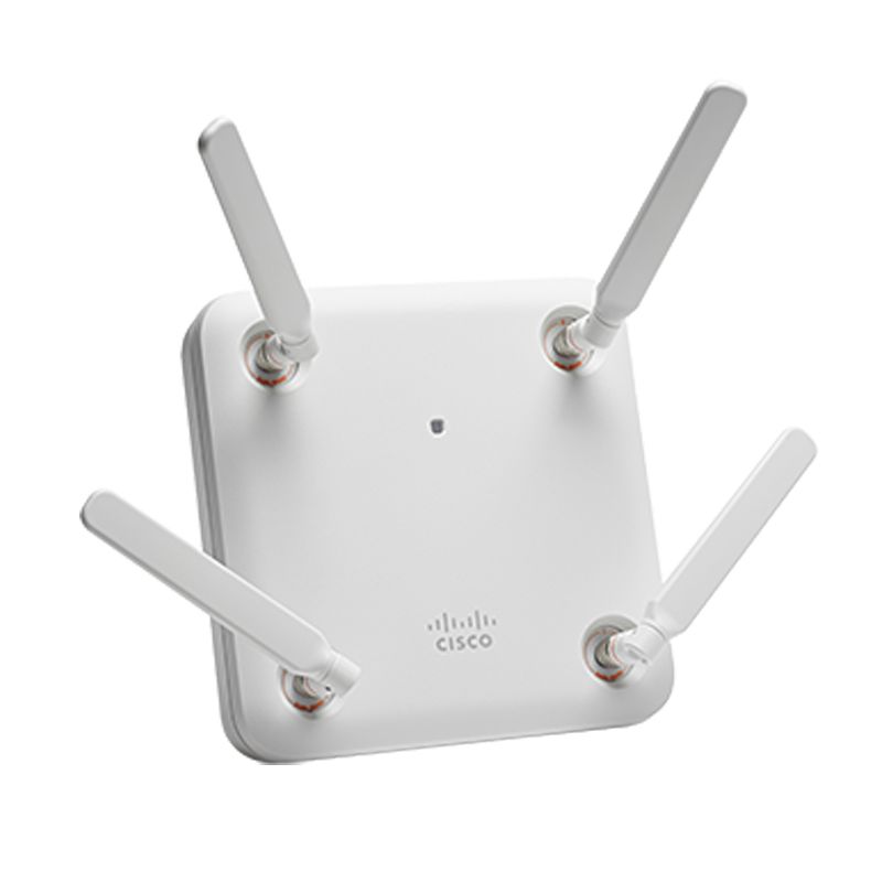
AIR-AP1852E-F-K9C Cisco Aironet 1852e 802.11ac Wave 2 4x4 MIMO AP
AIR-AP1852E-F-K9C is a 1852e indoor access point for separately purchased external antennas, supplied as a single-unit configurable K9C order for regulatory-domain token F. Verify destination approval, controller software, PoE mode, exact quantity, antenna or mounting bill of materials and the 30 April 2027 support cutoff before purchase.
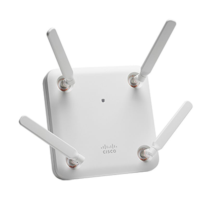
AIR-AP1852E-E-K9 Cisco Aironet 1852e WiFi 5 Access Points
AIR-AP1852E-E-K9 is a 1852e indoor access point for separately purchased external antennas, supplied as a single-unit fixed-domain K9 order for regulatory-domain token E. Verify destination approval, controller software, PoE mode, exact quantity, antenna or mounting bill of materials and the 30 April 2027 support cutoff before purchase.
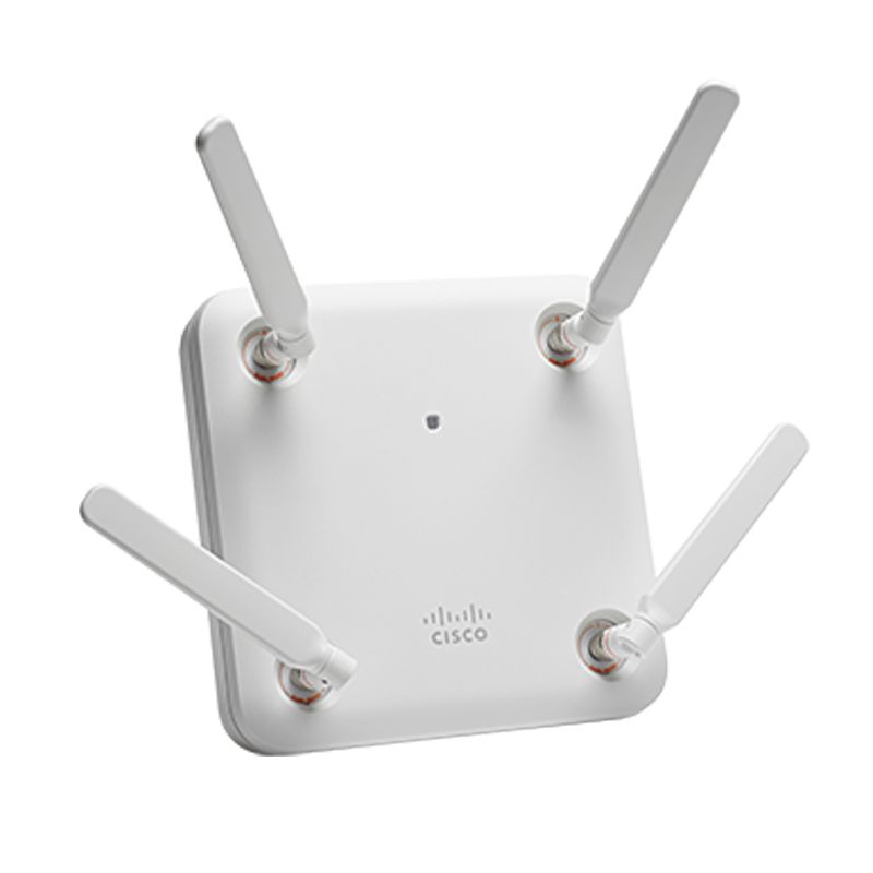
AIR-AP1852E-A-K9C Cisco Aironet 1852e 1.733Gbps Thoughput AP
AIR-AP1852E-A-K9C is a 1852e indoor access point for separately purchased external antennas, supplied as a single-unit configurable K9C order for regulatory-domain token A. Verify destination approval, controller software, PoE mode, exact quantity, antenna or mounting bill of materials and the 30 April 2027 support cutoff before purchase.
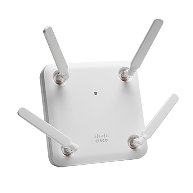
Cisco AIR-AP1852E-UXK9 Aironet 1852E Universal-Domain Access Point
AIR-AP1852E-UXK9 is Cisco's single-unit Aironet 1852E Universal Domain access point with external antennas; the external-antenna design requires a separately validated antenna and RF plan.
AIR-AP1852E-E-K9C Cisco Aironet 1852e Dual-band 4x4 MIMO AP
AIR-AP1852E-E-K9C: Configurable AP and antenna package rollback. Verify the exact PID, regulatory state and acceptance evidence before purchase.