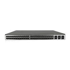
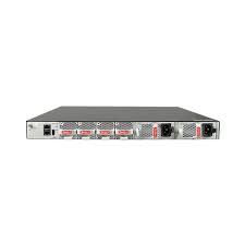
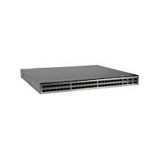
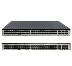
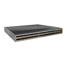
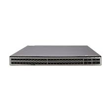
HUAWEI CE6863-48S6CQ-K CE6800 Series Switches

- 763 412 7282
- +86 010 69614620
CE6863-48S6CQ-K Buying Guide
Huawei CE6863-48S6CQ-K Switch is listed by YYST Global for buyers looking for HUAWEI CE6800 Series Switches. CE6863-48S6CQ-K HUAWEI enterprise network switch for network refresh projects. Contact YYST Global for stock, lead time and quote support. The listed condition is New Factory Sealed. The reference price is US$ 488.00. Contact our sales team to confirm stock, lead time, warranty and configuration before ordering.
- Model: CE6863-48S6CQ-K
- Brand: HUAWEI
- Category: Huawei CE6800 Series Switches
- Condition: New Factory Sealed
- Reference price: US$ 488.00
CE6863-48S6CQ-K Overview
CE6863-48S6CQ-K is a HUAWEI enterprise network switch listed by YYST Global for campus switching, data center expansion, spare replacement and network refresh projects. This page is intended for buyers comparing replacement parts, project supply, spare inventory and quote options.
YYST Global helps enterprise customers confirm model information, product category, condition, availability and sourcing route before purchase. For time-sensitive projects, send the model number and required quantity so our sales team can check stock, lead time and compatible alternatives.
Product name: Huawei CE6863-48S6CQ-K Switch. Category: Huawei CE6800 Series Switches. Condition: New Factory Sealed.
CE6863-48S6CQ-K Specification
| Exact model | CE6863-48S6CQ-K |
| Product role | Fixed data center access switch |
| Access ports | 48 x 25GE SFP28 |
| Uplink ports | 6 x 100GE QSFP28 |
| Dimensions (W x D x H) | 442 x 420 x 43.6 mm |
| Fully configured weight | 7.8 kg |
| Operating voltage | 90-290 V AC |
| Maximum power consumption | 384 W |
| Operating temperature | 0 to 40 degrees C at 0-1,800 m |
| Storage temperature | -40 to +70 degrees C |
| Relative humidity | 5%-95% RH, non-condensing |
| Airflow option | Select the matching fan and power airflow direction for the deployment |
| Automation and maintenance | FTP/TFTP transfer, BootROM and remote upgrade, hot patch, operation logs, rollback and ZTP |
| Security and access control | 802.1X, DoS/ARP/ICMP protection, port isolation, AAA, RADIUS and HWTACACS |
| Official manufacturer reference | Huawei CloudEngine 6863-K Data Center Switch Datasheet |
| Procurement validation | Confirm exact suffix, regional variant, power and airflow option, licenses, accessories, software compatibility, warranty and lead time before purchase. |
CE6863-48S6CQ-K
Version Mapping
Table 3-225 lists the mappings between the CE6863-48S6CQ-K and software versions.
Device Series | Sub-series | Device Model | Short Name | Supported Version |
|---|---|---|---|---|
CE6800 | CE6863 | CE6863-48S6CQ-K | CE6863K | V200R019C10 and later |
Appearance and Structure

The figures in this document are for reference only.
Figure 3-103 CE6863-48S6CQ-K

1 | Ground screw | 2 | Equipment serial number (ESN) NOTE: You can scan the code to view the ESN and MAC address of the switch. |
3 | Console port | 4 | ETH management port (RJ45) |
5 | USB port | 6 | Fan slot 1 Applicable fan modules: |
7 | Fan slot 2 Applicable fan modules: | 8 | Fan slot 3 Applicable fan modules: |
9 | Fan slot 4 Applicable fan modules: | 10 | Power supply slot 1 Applicable power modules: |
11 | Power supply slot 2 Applicable power modules: | 12 | Forty-eight 10GE/25GE SFP28 Ethernet optical ports Applicable modules and cables:
NOTE: When a port works at the rate of 25 Gbit/s, it supports only 1 m SFP28 high-speed cables, and these cables can only be used as stack cables or M-LAG peer-link interface cables. When a 25GE port is configured to work at 10 Gbit/s using the port mode 10g command, the port supports 1 m, 3 m, and 5 m 10G SFP+ high-speed cables. |
13 | Six 40GE/100GE QSFP28 Ethernet optical ports Applicable modules and cables:
| 14 | Three port-side mounting holes for mounting brackets |
15 | Two middle mounting holes for mounting brackets | 16 | Equipotential bonding Ground screws for a ground cable with a two-hole OT terminal |
17 | Four power-supply-side mounting holes for mounting brackets | - | - |
Slot Description
Power Slots
Each of the CloudEngine 6800 series switches has two power module slots and supports pluggable power modules. A chassis can use one or two power modules. In particular, dual power modules provide higher reliability.
The CloudEngine 6800 series switches support 1+1 backup of power modules.
- When both power modules are working properly, each of them provides half of the power required for the chassis.
- When one power module fails, the other one provides all power required for the chassis.
All power modules of the devices are hot swappable.
Fan Slots
Each of the CloudEngine 6800 series switches has four fan slots in which fan modules can be installed to cool the chassis, ensuring efficient heat dissipation and system stability.
It is recommended that four fan modules be properly installed on a switch to ensure normal switch operating. The device supports four pluggable fan modules that work in hot standby mode. The system can operate properly for a short time after a single fan module fails. You are advised to replace the faulty fan module immediately.
All fan modules are hot swappable.
Heat Dissipation System
The cooling system of the CloudEngine 6800 series switches uses front-to-back or back-to-front airflow depending on the airflow direction of the power modules and fan modules used.
- Front-to-back airflow: Power modules and fan modules with front-to-back airflow are identified by
. Air flows into the chassis from the power supply side and is exhausted from the port side, as shown in Figure 3-104 (using a CE6863 chassis as an example).
- Back-to-front airflow: Power modules and fan modules with back-to-front airflow are identified by
. Air flows into the chassis from the port side and is exhausted from the power supply side, as shown in Figure 3-105 (using a CE6863 chassis as an example).
Figure 3-104 Front-to-back airflow for port-side exhaust

Figure 3-105 Back-to-front airflow for port-side intake

The airflow direction of the power modules and fan modules required on the CloudEngine 6800 series switches depends on how the device is installed in a cabinet. Typically, cabinets in a data center have cold air flowing in from the front and hot air exhausted from the back. If a switch is installed with the power supply side facing the front and the port side facing the back, the switch needs to adopt fan modules and power modules with front-to-back airflow.
Power modules and fan modules using forced air cooling on a switch must have the same airflow direction. If a switch adopts power modules with back-to-front airflow, the switch must use fan modules with back-to-front airflow as well.
Indicators
Figure 3-106 Indicators on the CE6863-48S6CQ-K rear panel

Figure 3-107 Indicators on the CE6863-48S6CQ-K front panel

Table 3-226 Indicator description
No. | Indicator | Name | Color | Status | Description |
|---|---|---|---|---|---|
1 | SYS | System status indicator | Green | Off | The system is not running. |
Fast blinking | The system is starting. | ||||
Slow blinking | The system is running normally. | ||||
Red | Steady on |
| |||
2 | MST | Stack master/slave indicator NOTE: In V200R003C00 and later versions, you can use the dfs-master led enable command to enable the stack master/slave indicator to display the DFS group master and backup status. After the stack master/slave indicator is enabled to display the DFS group master and backup status, the stack master/slave indicator on the DFS master device is steady on and that on the DFS backup device is off. | Green | Off | The switch is not a stack master. |
Steady on | The switch is a stack master or standalone switch. | ||||
3 | ID | ID indicator | Blue | Off | The ID indicator is not used (default state). |
Steady on | The indicator identifies the switch to maintain. The ID indicator can be turned on or off remotely to help field engineers find the switch to maintain. | ||||
4 | - | Service port indicator (10GE/25GE optical port) NOTE: Each 10GE/25GE optical port has two single-color indicators. The one on the left is the ACT indicator (yellow), and the one on the right is the LINK indicator (green). Arrowheads show the positions of ports. A down arrowhead indicates a port at the bottom, and an up arrowhead indicates a port at the top. | Green | Off | No link has been established on the port or the port has been shut down. |
Steady on | A link is established on the port. | ||||
Yellow | Off | The port is not sending or receiving data. | |||
Blinking | The port is sending or receiving data. | ||||
5 | - | Service port indicator (40GE/100GE optical port) NOTE: Arrowheads show the positions of ports. A down arrowhead indicates a port at the bottom, and an up arrowhead indicates a port at the top. | Green | Off | No link has been established on the port or the port has been shut down. |
Steady on | A link is established on the port. | ||||
Blinking | The port is sending or receiving data. | ||||
6 | L/A | ETH management port indicator | Green | Off | No link is established on the port. |
Steady on | A link is established on the port. | ||||
Blinking | The port is sending or receiving data. | ||||
7 | USB | USB-based deployment indicator | Green | Off | USB-based deployment is disabled (default state). |
Steady on | USB-based deployment has been completed. | ||||
Blinking | The system is reading data from a USB flash drive. | ||||
Red | Steady on | USB-based deployment has failed. |
CE6863-48S6CQ-K Warranty
 | Low Price Guarantee |  | Quality Assurance |
 | 100% Money Back Guarantee |  | Commodity Refund Guarantee |
 | Diversified and Flexible Transportation Services |  | Standard Policy |
CE6863-48S6CQ-K FAQ
What is CE6863-48S6CQ-K?
Huawei CE6863-48S6CQ-K Switch is a HUAWEI CE6800 Series Switches product supplied by YYST Global for enterprise IT procurement and infrastructure projects.
What interfaces and ports does CE6863-48S6CQ-K provide?
For CE6863-48S6CQ-K, the official specification lists access ports as 48 x 25GE SFP28. Confirm the exact SKU, suffix and hardware revision against the official manufacturer reference before ordering.
What are the physical specifications of CE6863-48S6CQ-K?
For CE6863-48S6CQ-K, the official specification lists dimensions (w x d x h) as 442 x 420 x 43.6 mm. Confirm the exact SKU, suffix and hardware revision against the official manufacturer reference before ordering.
Is CE6863-48S6CQ-K available from YYST Global?
CE6863-48S6CQ-K is listed as in stock at YYST Global. Contact the sales team to confirm the required quantity, exact configuration, delivery destination and current lead time before ordering.
What is the price of CE6863-48S6CQ-K?
The current reference price for CE6863-48S6CQ-K is US$ 488.00. Final pricing can change based on stock, quantity, configuration and delivery destination.
Related products
Related CE6863-48S6CQ-K
Huawei CE6881H-48S6CQ-K Switch
CE6881H-48S6CQ-K HUAWEI enterprise network switch for network refresh projects. Contact YYST Global for stock, lead time and quote support.
Huawei CE6880-48S4Q2CQ-EI Switch
CE6880-48S4Q2CQ-EI HUAWEI enterprise network switch for network refresh projects. Contact YYST Global for stock, lead time and quote support.
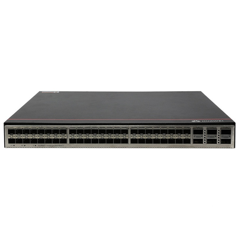
CE6881-48T6CQ-K CloudEngine 6800 series switches
CE6881-48T6CQ-K HUAWEI enterprise network switch for network refresh projects. Contact YYST Global for stock, lead time and quote support.
Huawei CE6866-48S8CQ-K Switch
CE6866-48S8CQ-K HUAWEI enterprise network switch for network refresh projects. Contact YYST Global for stock, lead time and quote support.
Huawei CE6863H-48S6CQ-K Switch
CE6863H-48S6CQ-K HUAWEI enterprise network switch for network refresh projects. Contact YYST Global for stock, lead time and quote support.
Huawei CE6820H-48S6CQ-K Switch
CE6820H-48S6CQ-K HUAWEI enterprise network switch for network refresh projects. Contact YYST Global for stock, lead time and quote support.
Huawei CE6881-48T6CQ Switch
CE6881-48T6CQ HUAWEI enterprise network switch for network refresh projects. Contact YYST Global for stock, lead time and quote support.
Huawei CE6866-48S8CQ-P CloudEngine 6800 series switches
CE6866-48S8CQ-P HUAWEI enterprise network switch for network refresh projects. Contact YYST Global for stock, lead time and quote support.
